Last week i was alone at home since my parents had gone out to attend a marriage in mangalore.I was alone at home for about 10 days and had no college since there was our college ‘techfest’.i dont like attending ‘techfests’ on a shoestring budget,like the one in our college!!.there only a few things which fit into my definition of tech there!
So I was alone & bored and to get rid of my boredom and loneliness i wanted to do some fun project.i had a few hundred bucks with me,and i had an old luminaire (called jhoomer in hindi)-it had those bayonet mounted so called ‘zero watt’ incandescent bulbs. I consider incandescents a thing of the past as they are very inefficient and are energy guzzlers-they waste a lot of energy as heat.Infact they generate much more heat than they produce light!!!So i thought that replacing the incandescents with power LEDs which consume lower power and produce much more light.Also the light is much more soothing to the eye.
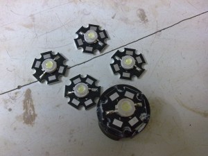
I went to the electronics heaven of mumbai-lamington road.with my friend Vijay to get some 1 watt LEDs.In my previous posts i have written about these LEDs and how to drive them.I got six 1 watt LEDs since my luminiare had six ‘arm’s.i could simply hook these leds to a wall wart of about 12 volts and a current rating of about 600 ma.hook it up in two parallel rows of three series LEDs .each LED requires a voltage drop of about 3.4v and a current of 300ma.that totals to about 10.2 volts and 600ma total power required. simple eh?? but that’s not the case these led are much more complicated devices as mentioned in the past posts.They require a constant regulated supply for stable and reliable operation. With the correct type of supply a long life can be expected of these LEDs.Usually these LEDs are rated for about 10,000 to 100,000 hours of operation.Thats miles ahead of the current fluorescent and incandescent technologies.
So i had to make the power supply for these LEDs so as to ensure reliable operation.I had a few LM3404 samples i had received from National semiconductor lying around.Its a buck converter based constant current source LED driver.It has an internal MOSFET capable to switch up an amp of current. requires very few external components for operation.Hence is ideal for my project.Also since it’s switching based device it has very high efficiency.So my objective of going green is fulfilled too.The rest of the components used have been salvaged from old electronics-old PC SMPS,old nokia charger,cordless phones,TV video games,FM radio,DVD writer etc.I firmly beleive in recycling!!.
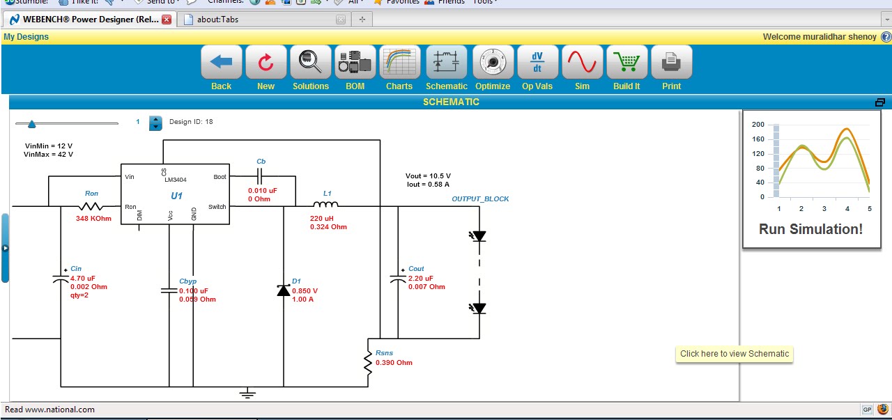
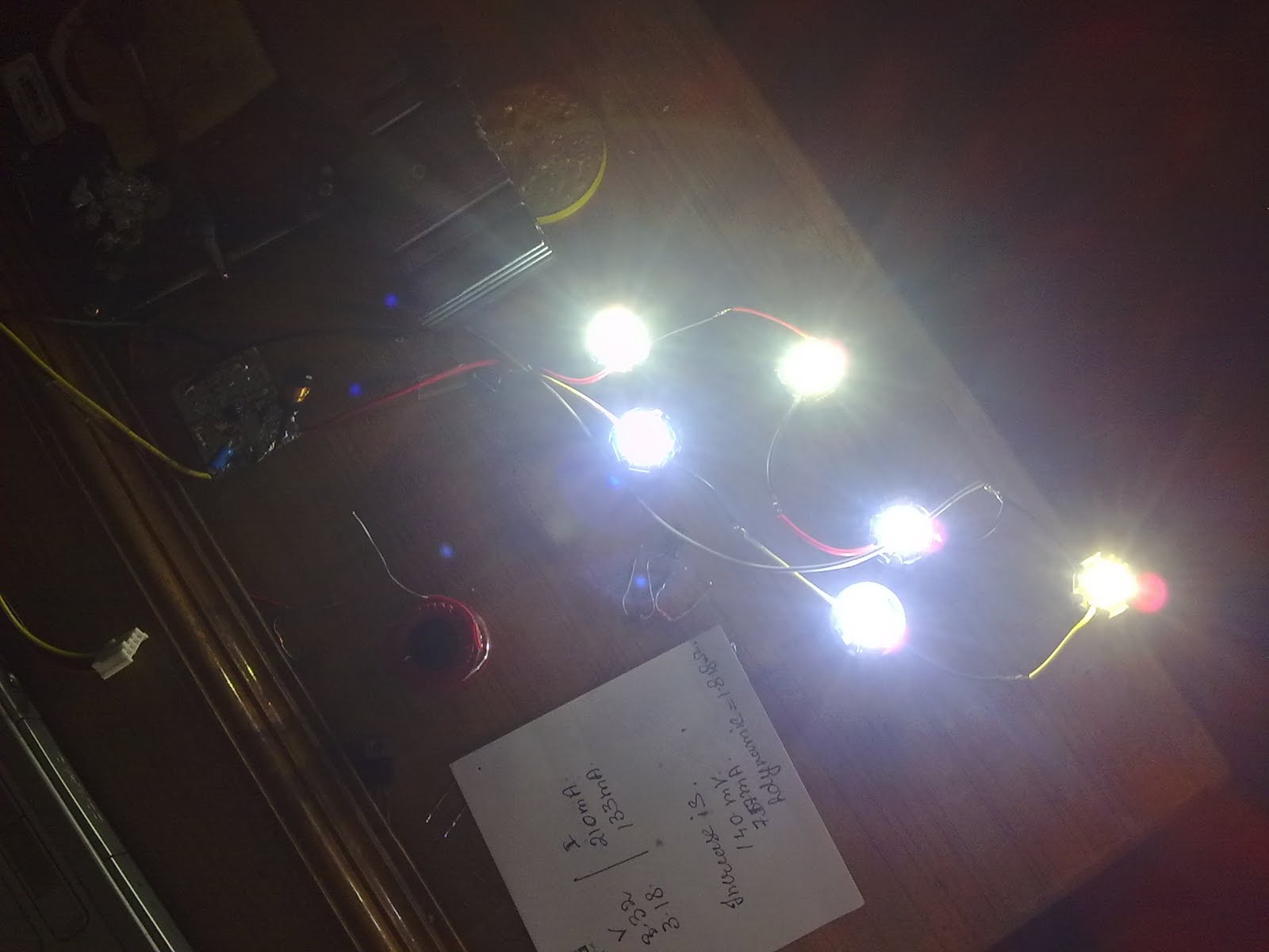
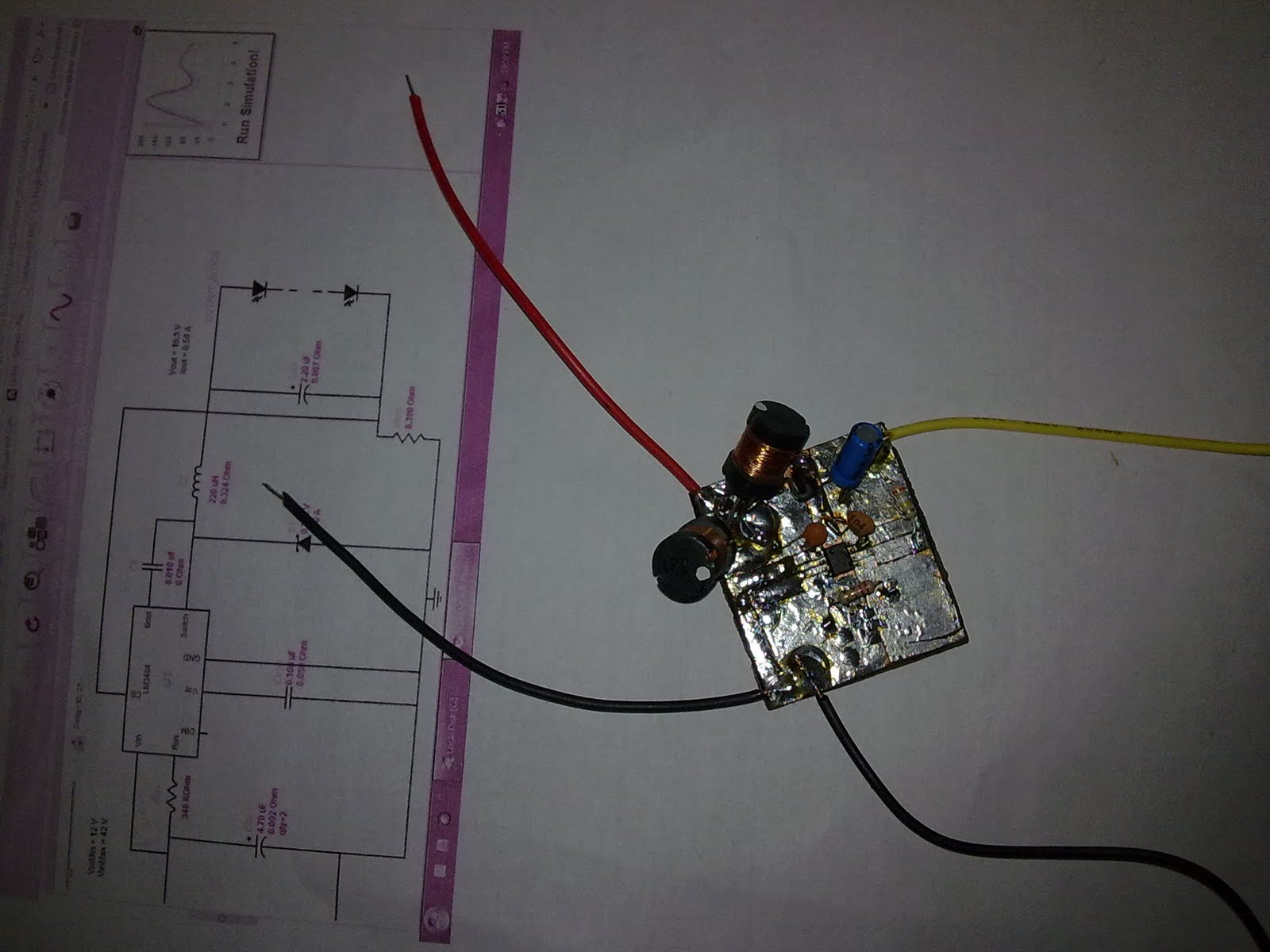
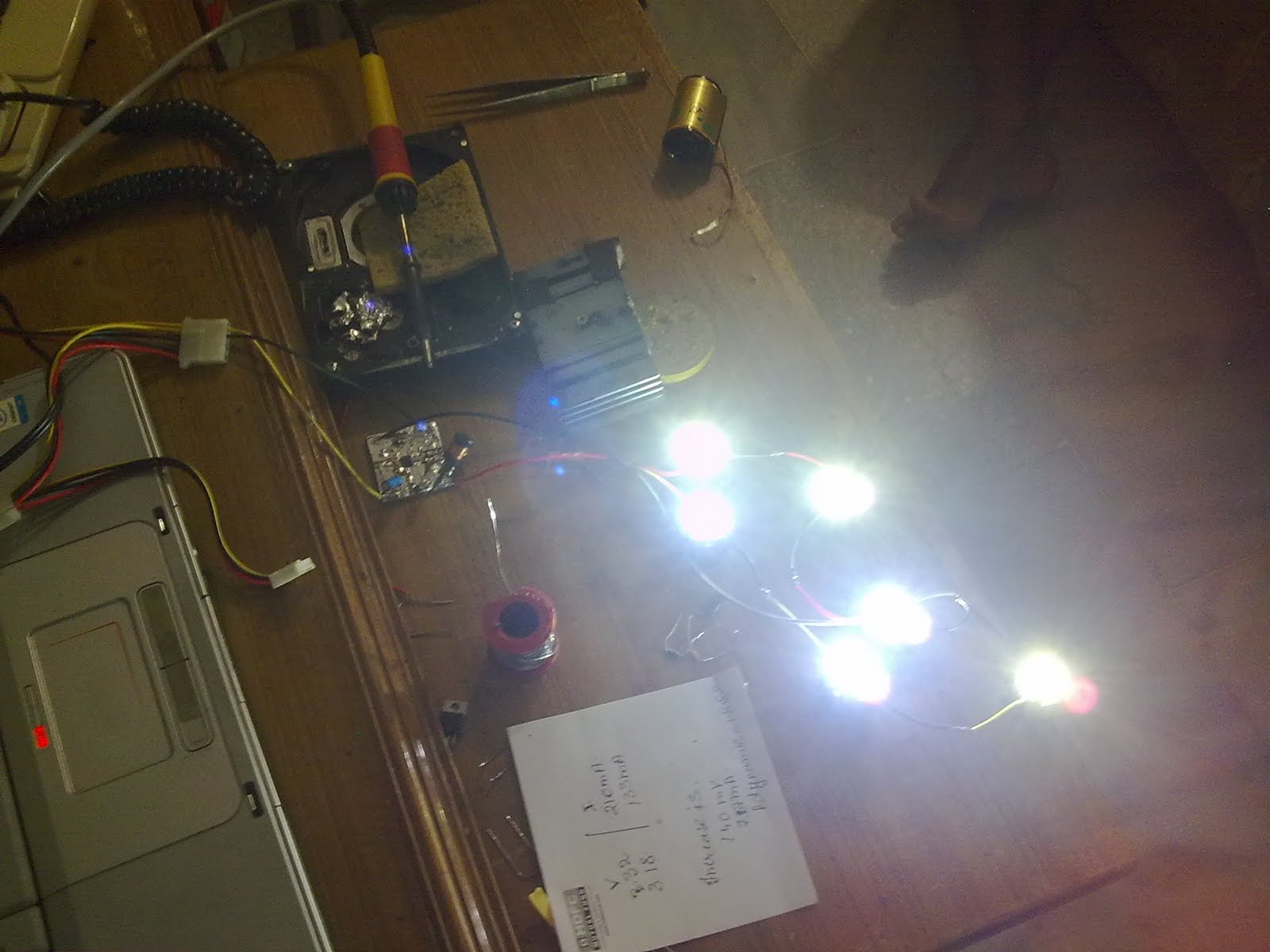
Now i checked out the datasheet of the LM3404,there were a lot of formulae and stuff on how to calculate the values of the various components used in the circuit.I found it difficult to get the accurate values of these components .I was also not too sure about the values being accurate. so i tried out the webench tools from National Semiconductor.These are great free tools from national which help in designing circuits based on their ICs.registration is required to use these tools which is also free. now on the webench designer page for LM3404 there were fields for the forward voltage of the LEDs,forward current,etc.I had no exact values for my LEDs since the guy whom i brought it from just referred to the as chinese made 1w led.So i assumed that it would be having a forward voltage of 3.4v and a current of 350ma.To confirm my assumption i had to check these specs with my multimeter.the volatge across the LED was 3.18v @133ma and 3.32v @210ma.I used a constant current supply mentioned in my provious post on power LEDs to check the voltage across the led.These values also help in determining the Rdyanmic-the dynamic resistance of the LED also known as ESR(equivalent series resistance).usually it is 1-2 ohms for power LEDs. In my case it was 1.81 ohms.The ESR can be calculated by measuring the increase in forward voltage drop dividedby the increase in current. For example, if the forward voltage drop increases by from 3.5V to 3.55V (a 50mV increase) when the forward current goes from 10mA to 20mA (a 10mA increase), the ESR will be 50 mV/10mA=5 ohms.I’ll be using a 12volt-1amp Wall wart from a deceased cordless phone as power souce for the LED driver cicuit.Take a printout of the circuit designed by the webench designer,as you’ll be needing it for further reference.here’s mine. there are 2 strings of three LEDs in parallel at the output block.
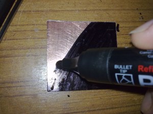
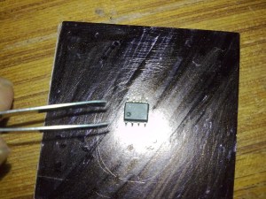
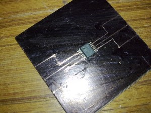
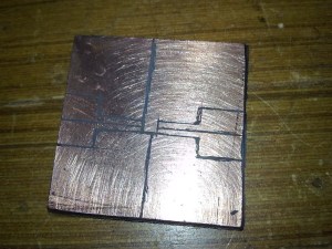
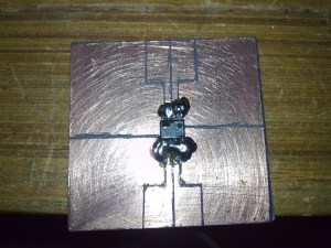
then i drew a few lines between the leads of the chip using the pointed end of one leg of the tweezer as shown.this exposes the copper of the pcb.Here the chip acts as the stencil.the chip can be held in place using an end of a toothpick.
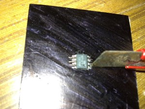

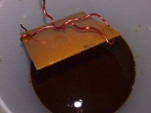
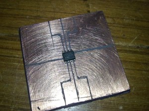
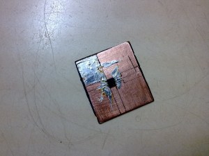
extend the lines further and widen these lines if possible,to allow for use of thru hole components.now prepare the etching solution.I prefer ferric chloride. hold the pcb by means of a ‘holder’ i hav made one out of thick laminated copper wire.dip it into the etching soln.keep stirring continously.sometimes heating may also be required for speeding up the process.after the etching is done and all the bare copper is removed, remove the marker ink using acetone(sold as nail paint remover). your pcb is ready. check for any short circuits between the various parts of the pcb usin multimeter.i kept a small patch of copper shorted with the ground under the pcb to act as a heatsink since this chip has a powerpad at the bottom which is grounded.this power pad help dissipate heat as well as increase the sink/source capability of the chip.

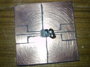
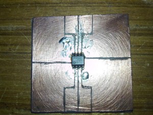
first of all hold the chip in place using a tootpick on the prepared PCB. solder just the pin no.1.this helps to keep the chip in place.now now solder the pin no.8. now the rest of the pin are soldered by placing a blob of solder on all the four pins on one side .then the blob maybe sucked out using desoldering braid which leaves only the required quantity of solder on the pad.the process is repeated on the other side as well. check for the continuity between the pads and the pins by a multimeter,once confirmed.proceed to soldering the other components.
slightly bend the legs of the thru hole components then tin them.then solder these components over the
now try applying a thin layer of solder over the pcb.this helps in increasing the current carrying capacity of the pcb as well as to prevent oxidation of the copper.solder the components on the pcb as shown.a thin sticky layer of slag was formed on the pcb while soldering.this can be easily removed by rubbing a peice of cotton soaked in acetone.
i use this technique to ‘surface mount’ thru hole devices.this technique is great for prototyping.this method can also be used for ‘permanentizing’ the circuit. heres the completed circuit. before testing the circuit do remember to remove the slag as i can form a capacitor between the pins.this stray capacitance can damage the circuit and lead to malfunction and i learnt this the hard way.I had to sacrifice a IC to this stray capacitance :(.
the led driver circuit is ready now.

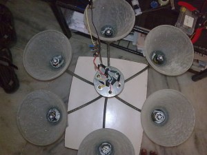
Now these LEDs cary a huge amount of power for their size.They generate some heat so heat sinking is required to prevent any damage due to overheating.I got some small heatsinks that could fit in the bulbholders themselves so there’s no need to reengineer the LED mount.the LEDs were ‘stuck’ to the heatsinks by means of heats ink compound.a small container of this thermal compound would suffice and the cost just 10 bucks.i would suggest polishing the surface of the heatsink before applying the thermal paste.It is not necessary though.Just to be on the safer side i polished the surface of the heatsink with some sand paper.a very small amount of thermal paste is applied on the heatsink.so as to form a very thin layer. the LED is the placed on the heatsink and a small amount of force may be applied so as to place the LED firmly in place.this step is repated for all the leds.


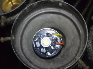
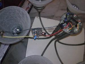
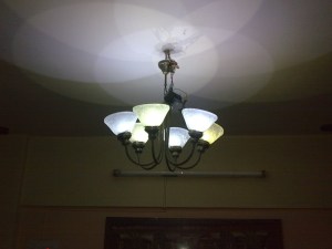
i managed to squeeze the LEDs fitted with the heatsink into the bayonet mountings of the incandescent bulb.this made my job of mounting the LEDs a bit easy.a lot of improvisation might be needed here.i also rewired the whole Luminaire. since the wire was old and was oxidised. i connected the each set of 3 LEDs in series. this gave me 2 strings of 3 series LEDs. i connected these two strings in parallel. i first tested the circuit with the 12v out from an computer SMPS.the yellow wire from the SMPS is the +12v while the black wire is the ground. the test was sucessfull so i proceeded to mounting the circuit.i attached a barrel plug connector to driver circuit so as to allow the connection of a standard wall wart supply. i used a 12v-1amp adapter that was used as a supply for a cordless phone. i mounted the circuit on the wallwart itself with some insulation tape.the supply for the adapter is given from the mains .after testing the circuit for another hour to check the stability i reassembled the luminaire and hung it back up on the ceiling.
Note:i was unable to upload the photos of soldering the through hole components on the SMD pcb due to some technical glitches.sorry for the incompleteness.will upload the pics as soon as possible.Also thanks to mandar for staying up late until the wee hours of morning and for that can of redbull which helped me stay up that late 😉

Leave a comment