The Idea for this post struck me on a hot summer day here in California, it was a 100F outside and my phone mounted on the car dashboard wouldn’t charge as fast(like 1% in like 30 minutes) although the phone indicated that it was in fast charge mode and I could not see any other issues with the charger or the charging cable, maybe the heat was affecting the charge rate?, I had to find out for myself.
There are two broad Fast charging technologies out there, Qualcomm’s QuickCharge and Oppo’s VOOC charging. Most mainstream smartphone brands use Quickcharge, while smartphone brands like Oppo and One plus use VOOC based charging technology. Both technologies are really interesting and solve the same problem using different approaches. This post is primarily about Qualcomm’s quick charge 2.0, which was implemented in the Galaxy Note 4(circa 2014) that I had on hand. Newer phones use QC 3.0 or more recently QC 4.0.
Instrumentation:
I came across this really neat little LTC2943 chip from Linear Tech (now part of Analog Devices). I think the target application for this chip is laptop Lithium Ion battery charge monitoring, but it should work well for this application.
The schematic is as shown below, basically, the Rsense is hooked in between the Charger Side Vbus and the Phone side Vbus

I then needed a device that could talk to the LTC2943 and log the data to my computer over USB. Some Arduino code running on the Atmel Atmega328p Xplained Mini did the trick. The Xplained board also has debugging capabilities which made prototyping easier. the debugger onboard can also act as a USB to serial bridge so all I needed to do was ensure the output in proper format and I could copy the data from the serial terminal to a CSV for easier processing.

The actual breadboard setup(this is a quick and dirty setup that I came up with, worked well for this test)
Once the instrumentation was in place I basically ran the test twice once with quick charge enabled and once without.
Analysis:
I wrote some quick python code to analyze the data from the two test runs. Check the screen capture below for the results
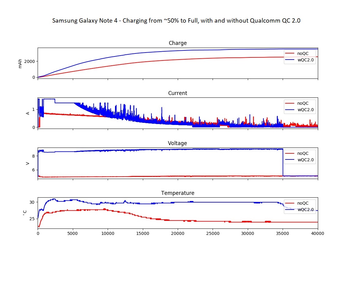
A few quick observations from the data (tl;dr):
- Quick charge seems to violate the USB Vbus voltage spec
- Quick charge uses the D+ and D- for voltage negotiation, hence you wouldn’t risk damaging a non-QC device by plugging into a QC compatible charger
- Quick charge algorithm seems to back’s off on the current under the following conditions
- When the phone is being used or if the battery is being loaded above a certain threshold
- when the temperature crosses a certain threshold, this is to prevent battery over heating
- Quick charge is less efficient than regular USB charging, this is evident from the higher amount of heat being dissipated by the end device

Additional references
- Interesting TI app note on implementing QC 2.0
- Github link to the firmware/software/hardware used for this experiment: https://github.com/hmms/fast-charge-analysis

Leave a comment