In my earlier post i had made a gadget charger which could charge your mobile phone,ipod,or other gadgets.It was based on a rather simple chip -the humble 7805. Now lets move a step further and make a more efficient emergency charger. this charger is based on the lt1302 from linear technology. I had got as samples from linear.com samples service two lt1302 ics .the datasheet provided very promising numbers efficiency reaching nearly 87%!! wow!!!!that’s great.That means more charge gets into your gadget.
The IC is a boost converter IC .As the name suggests it boosts the input voltage.It forms a very simple switching mode power supply. From the datasheet i found that it can operate down to voltages as low as 2v.That means we will can use two 1.5v alkaline or 1.2v ni-mh rechargeablesas the power source(as the cells discharge their voltage falls below the rated volatge,Ni-mhs usually discharge down to 1.0 v per cell before they need a recharge).Now what exactly is a boost converter??? . A boost converter is a form of a smps.It’s basic circuit is as follows.

Basic boost converter
source:wikipedia
To understand better try wikipedia.what it basically does is it employs an inductor to store energy from supply as the switch switches on and off rapidly.This switching on-off happens at a very high frequency upto 310 khz in this case.The switch in the SMPS of your PC is usually a MOSFET or an IGBT.These devices can handle a huge amount of power i.e. upto 50A constant current and 200A transients!!.These devices have very low on state resistances usually 0.015-0.018Ω hence the power losses across these devices are less.A simple BC547 NPN transistor can handle upto a few hundred mA hence in comparison these devices have very high power rating.These switches are turned on-off by means of an oscillator connected to a comparator which takes feedback and adjusts the frequency accordingly.Thus modifying the pulse width depending upon the power requirement. This is called pulse width modulation.
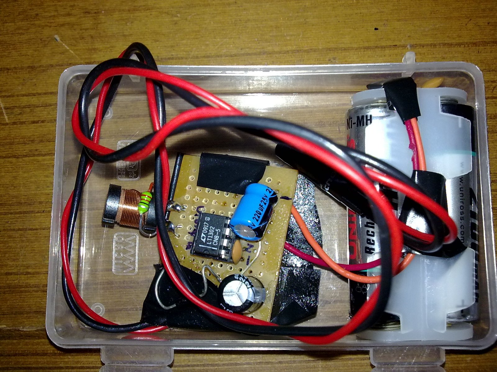
Enough basics.Back to our project now.All the switches,pwm comparators, etc are built right into the lt1302. a few external components are required such as a schotthy diode(warning do not use 1N400 series diodes they are designed to work at low frequencies and hence will not work.),power inductor(I salvaged mine from an old printer), a few caps and resistors,Oh and a perf board or pcb to mount them all.
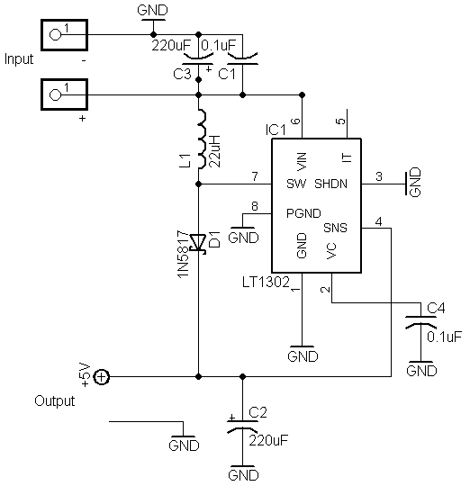
Here’s the schematic.

schematic for gadget charger using Lt1302.
The input capacitors are present for the noise suppresion. now when the circuit is given the supply the switch is off which charges the inductor through the sw pin now the switch turns on then the energey stored in the inductor along with the energy from the supply are fed to the output. the 220uf o/p smoothing capacitor is present for smoothing the output. the capacitor iaverages the output. a gives a good consistent output. The inductor should usually have very low dc resistance to reduce copper losses. The inductor should have a rated current of at least 2A. checkout the ones from coiltronics and coil craft.The output maybe connected to a usb female jack to charge your usb device such as a mp3 player or in my case it’s the nokia 2.5mm male charging connector.
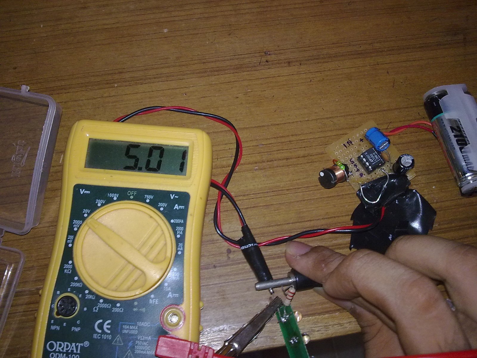
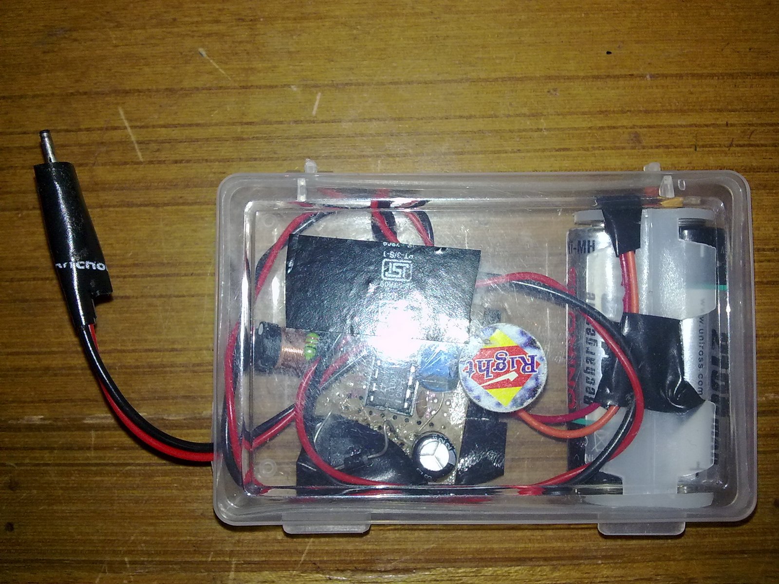
This charger has higher efficiency also the output of this circuit is 600ma max. so this can charge your device pretty quickly. my nokia n78 charges from near empty to full in about 2 hrs.compare that to a standard wall charger which takes 1.5 hrs for a full charge.Thats pretty good for a portable charger i think. I use 2100mAh Ni-Mh rechargeables as the power source.they last me for more than one full charge..the batteries and the inductors do get very hot when in use.you can leave the batteries in the circuit itsel when not in use since the quienscent or “housekeeping” currrent of this circuit is about a few hundred microAmps but this will drain the batteries eventually ,or better still you may include an on/off switch with the battery holder .i wrapped the whole circuit in insulation tape to protect it and increase the ruggedness.i did not find the inductor the correct value so i tied two inductors in parallel to get the desired value.Inductors in parallel are very much like reistance in parallel they follow similiar formula for calculation.

